Is it the SRAM or the decoder mux?

I didn’t get a chance to play with any hardware today, but I want to elaborate on the conclusion I came to previously. In my last post, after several diagnostics of the Tandy logic board, I concluded that the problem was a failed SRAM chip, specifically M6 – the “option” RAM. I still think this is the most likely culprit, but there is one other possibility: a bad decoder mux – M5 .

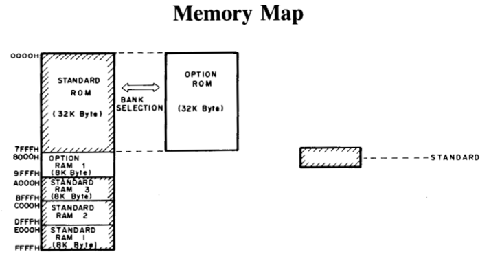
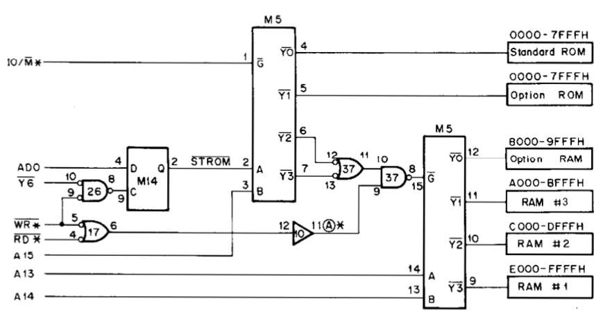
The Tandy 102 Technical Reference Manual describes the decoder circuit in great detail and provides the schematic. The decoder circuit uses a multiplexer (mux) to convert the top three bits of the address bus into individual chip enable signals. (Actually, the tech ref talks about generating eight enable signals for an earlier version of the 102 which used 4k SRAM chips.) I can see from the oscilloscope output that no chip enable signal is getting to the option RAM’s enable pin.

So, is the problem with the mux or the SRAM? Let’s list the clues:

  • M6 is getting proper power (Vcc = 5v)
  • M6 is properly connected to the address/data bus
  • M6 is never receiving a chip enable signal
  • All of the other SRAM chips are working properly
  • The M6 enable signal is high, but quieter than other SRAM’s enable lines
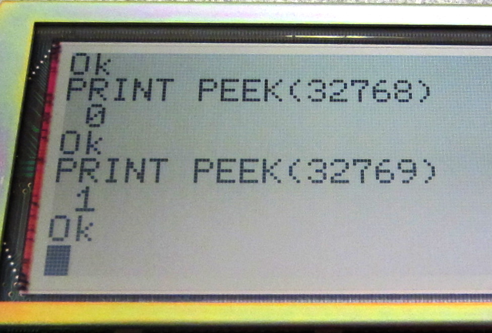
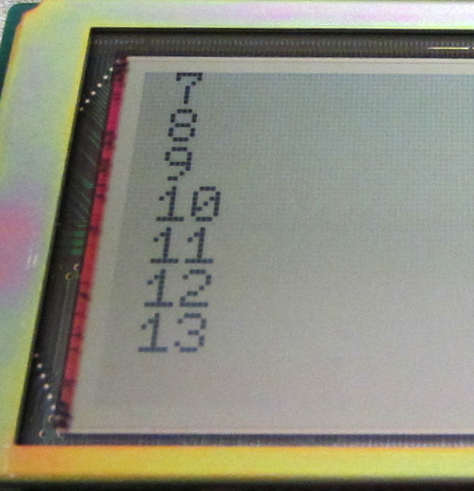
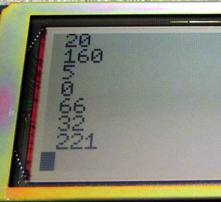
  • Attempting to read from M6 results in reading back the address lines

I find it unlikely that the mux (M5) would fail only on a single output pin and leave the others working (which they must be if the rest of the RAM works). Generally speaking, it’s more likely that a large-scale-integrated chip (like an SRAM) would fail versus a small-scale-integrated one like a mux.

Finally, there is the issue of the enable line noise. Here are the scope traces from before, with M6 above and M7 below:

Chip enable M6Chip enable M7

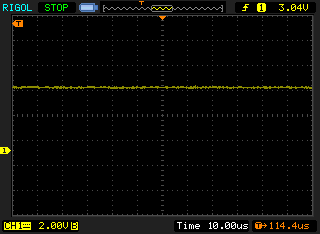
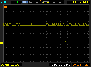
The enable line on the working chip shows a small amount of digital noise, where the presumably failed on does not. What could this mean? I’m not completely certain, but I expect that the noise is coming from within the inner workings of the SRAM and is bleeding into the enable line – not enough to affect the line, but present nonetheless. The non-working chip shows clean Vcc. No digital noise could be a sign that nothing is going on inside the chip.

So, that’s the reasoning behind my conclusion. Hopefully I’ll be able to break out the soldering iron soon and test my theory.

Tandy 102 RAM Exam

Here it is – taunting me!

Cold booted 24k
That horrible number: 21446 Bytes free.

The Tandy 102 (and the Tandy 100 which came before it), like most vintage 8-bit systems, have a very simple memory map:

Tandy 102 memory mapThe Intel 8085 (an 8080 derivative) has a 16-bit address space, meaning it can address up to 64k of physical memory space. The system ROM occupies the top (lowest-address) 32k of memory space and the SRAMs occupy the bottom (highest-address) space. The space in the middle, between 8000 and 9FFF, is a little bit special: it’s reserved for the “Option RAM”. When the Tandy 10o was originally introduced, it shipped with only 8k of RAM installed, but had sockets for up to 24k of additional RAM. When the 102 was later released, being an upgrade of the 100, it shipped with 24k installed and left a single space open for an additional 8k of RAM: the “Option” RAM.

Together all four 8k RAM chips provide the full 32k of RAM from address FFFF to 8000. (Note that all of these RAM address numbers are given in hexadecimal notation.) However, as the Tandy 100 OS and various other memory structures occupy some memory even on a freshly booted system, a 32k Tandy 100 will show 29314 bytes free. The sad 21446 in the bottom-right corner of my unit is the max free space on a 24k system, meaning that it has lost 8k of RAM – a full quarter of its precious memory.

Could there be something wrong with the way the OS is detecting the memory configuration? Let’s use BASIC to query the memory space where the RAM chips live, starting at the “top” of memory space:

Basic peeking

Right away, something isn’t right. What are the chances of two successive peeks at sequential addresses returning an incrementing series starting from zero? Lets keep poking. A quick BASIC program will read all addresses starting from 32768 (8000 hex):

10 FOR I = 1 to 8000
20 PRINT PEEK (32768 + I)
30 NEXT I

The results aren’t pretty:

Reading 8000

What in the world is going on?

The answer lies in the 80C85’s multiplexed data bus. The lower 8 bits (the least-significant bits) of the address bus are shared with the data bus. So, when accessing memory address 8000, the bottom 8 bits of the address bus are all zero. Then, after the address has been sent to the RAM chips and latched by the memory decoding circuit, the 80C05 reads the data lines; the RAM chip should have loaded an 8-bit data word onto these lines by now. However, if we have a faulty RAM chip, what’s left on the data bus is the lower byte of the address we read. Hence, as we increment the read address, the value we get from the PEEK also increments.

To confirm my suspicion, let’s try reading from a different RAM chip’s addresses:

Read A000

Random values – exactly what we would expect when reading from a random address inside a working RAM chip. So, what’s wrong?

There are several potential causes:

No power?

I pulled up the datasheet for the 8464 SRAM. Vcc is reading 5v and ground is continuous with a known ground point. Strike 1

Bad trace?

A member on the Club 100 mailing list said that it’s not uncommon for Tandy 100/102 logic boards to develop bad traces. I checked continuity on the address/data bus and found it continuous with working chips. Strike 2

Bad decoding circuit?

The Tandy 102 technical reference manuals (remember when you could get those?) lays out the memory decoding circuit.

Tandy memory decoder

A multiplexer is used to turn top three bits of the address bus into individual chip enable signals for the 4 RAM chips. With this circuit, even though all four chips are receiving the same address on the bus, only one of them is active at any time. So, if I probe the chip enable lines, I should be able to see the decoder circuit activating the right chip at the right time. Probing RAM chip M7 (the one we saw giving the expected random bytes earlier), we see the enable line periodically going low (this is a low-active line, meaning the chip is enabled when the line goes to ground).

Chip enable M7

However, when probing M6 (the option RAM) chip enable, the line never goes low.

Chip enable M6

In fact, we don’t even see the small amount of digital noise present on M7’s chip enable line. I was hoping to find a bad trace here, but checking from the decoder mulitplexer to the M6 chip enable line shows zero ohms: an intact trace.

So, faced with these facts I must conclude that I have a dead RAM chip. Luckily, 8k x 8 (8 thousand “words” by 8 bits) SRAM chips are still readily available. A quick check on ebay brings up a 3-pack for $10 with free shipping. If only we’d had RAM prices like that in the ’80s!

Retrochallenge 2016/10: The 8-bit hospital

Welcome to the 8-bit computer hospital.

The Patients

Patent number one is a 28-year-old 32kB Tandy 102 suffering from acute amnesia. Patent reports being in the middle of some casual BASIC coding when it suddenly crashed and erased the program. Upon cold-boot, it couldn’t remember anything from its upper 8k of RAM. In fact, the patient insists that it only ever had 24kB. When asked, under hypnosis, to recall anything from 8000 to 9FFF, it simply repeats the question.

The Tandy 102 has undergone oscilloscopic imaging to determine the extent of memory damage. It appears that chip M6 has failed, leaving the patient one quarter of its RAM dead.

Patient number two is a 33-year-old Atari 400. This Atari has previously received several elective procedures, including a RAM augmentation, an RF-ectomy, and a keyboard graft. Patient is here to correct a previous composite video surgery that left it with poor luminance. While on the operating table, patient has also elected to receive a stereo pokey implant.

Retrochallenge 2016/10 begins!

Retrochallenge 2016/10 has been announced! Go to retrochallenge.org for more details. If you’re not familiar with retrochallenge, it’s basically a month-long excuse to monkey with vintage computers.

I’ve never participated in retrochallenge before. I’ve always been interested in vintage computing, but only recently became more active in the hobby. I figured I’d have to wait until next year to do a retrochallenge, so I was excited to see the announcement. My challenge will most likely revolve around much-needed repairs and upgrades to my Atari 400 and Tandy model 102.

The Atari I’ve had since I was about 6 years old. My dad upgraded it to 48k and built an awesome external 800 keyboard. However, it only had RF video out. I’ve tried in the past to convert it to composite via a drop-dead simple tap of the signal, but I have never gotten good results. I also have a dual-pokey mod to install and a bare SIO2SD to get connected and working.

The Tandy 102 is the most recent addition to my vintage machine collection. It’s a 32k machine, but last month it suffered an unexplained reboot followed by a loss of 8k of RAM. I’ve done a bit of investigating, but I have some soldering ahead to get this unit back to 32k.