In they early 1980s, computers were hard. They were, on the whole, large, expensive, clunky, and difficult to operate. Graphical user interfaces were not yet a thing, and manufacturers really didn’t have a good handle on how to make computers easy to use and understand yet.
Tandy’s general approach to marketing computers had been to leverage their massive network of Radio Shack stores as both sales channel and service/support facilities. The pitch was simple: If you ever have any problems with your Tandy/Radio Shack computer, bring it to your local store (they had thousands, so a large portion of the U.S. population was easy driving distance to one), and a friendly technician would help you with it. Sure, this kind of support load would be a losing proposition today, but back when making computer hardware was actually profitable, companies viewed support as essential to making the hardware sale.
One of the ways that its designers tried to simplify the Model 100 family, was by shipping all software in the form of ROM modules. This had a couple of clear advantages over other systems of the time:
- Software loaded instantly
- No disks to lose or fail
- Copy protection
But it had one fairly big drawback: The user had to actually install hardware to install software. Clearly, this would have been intimidating to a lot of potential users, so Tandy attacked this problem in two ways. First, software that you bought from Radio Shack would be installed by the sales tech at no charge. And, second, the machine used a special snap-in module socket instead of a chip with pins. This allowed the module to be installed without risk of bending or breaking the fragile pins on a traditional ROM IC.
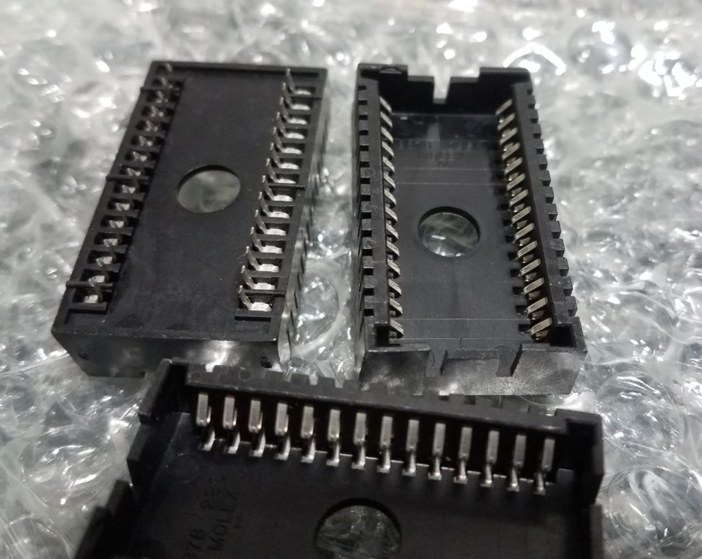
This module socket is the Molex 50-39-5288. Like everything in this project, it’s obsolete and not manufactured anymore.
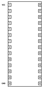
 Of course, these special modules didn’t share the normal JEDEC pinout of the common DIP-28 IC ROMs, oh, no. There were a couple of key differences, just to shake things up, I guess. But the only thing I care about at this stage is power and ground, and they’re still located in the usual places. So, if I can get my hands on one of these Molex sockets, I can easily supply 5 volts to the REX while flashing the CPLD. I powered the first 2 boards in the Tandy itself while flashing, and that’s a bit clunky and slightly nerve-wracking. This will be better.
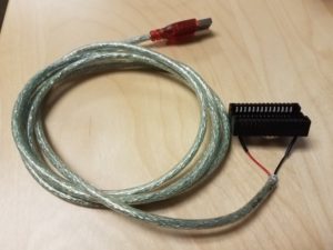
 Again, a kind member on the M100 list had a good stash of these sockets and sold me a few really cheap (thanks Brian!) so all I need to do is wire power and ground to it as indicated above and Bob’s my uncle! Luckily, USB is a cheap and easy 5 volt source and I have a ton of cables lying around ready to be hacked.
What kind of modules were used with these sockets (part numbers)? Looks a little bit like two-sided vaguely PLCC-style thingies were intended.
I think Molex sold some chip carriers that were intended to be used with these. You can see them in the datasheets. But in the Tandy case, basically two types were used: castellated PCBs and flexible circuit boards w/ exposed traces.