I didn’t get a chance to play with any hardware today, but I want to elaborate on the conclusion I came to previously. In my last post, after several diagnostics of the Tandy logic board, I concluded that the problem was a failed SRAM chip, specifically M6 – the “option” RAM. I still think this is the most likely culprit, but there is one other possibility: a bad decoder mux – M5 .
The Tandy 102 Technical Reference Manual describes the decoder circuit in great detail and provides the schematic. The decoder circuit uses a multiplexer (mux) to convert the top three bits of the address bus into individual chip enable signals. (Actually, the tech ref talks about generating eight enable signals for an earlier version of the 102 which used 4k SRAM chips.) I can see from the oscilloscope output that no chip enable signal is getting to the option RAM’s enable pin.
So, is the problem with the mux or the SRAM? Let’s list the clues:
- M6 is getting proper power (Vcc = 5v)
- M6 is properly connected to the address/data bus
- M6 is never receiving a chip enable signal
- All of the other SRAM chips are working properly
- The M6 enable signal is high, but quieter than other SRAM’s enable lines
- Attempting to read from M6 results in reading back the address lines
I find it unlikely that the mux (M5) would fail only on a single output pin and leave the others working (which they must be if the rest of the RAM works). Generally speaking, it’s more likely that a large-scale-integrated chip (like an SRAM) would fail versus a small-scale-integrated one like a mux.
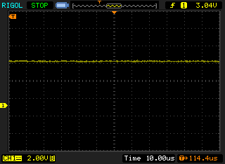
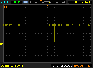
Finally, there is the issue of the enable line noise. Here are the scope traces from before, with M6 above and M7 below:
The enable line on the working chip shows a small amount of digital noise, where the presumably failed on does not. What could this mean? I’m not completely certain, but I expect that the noise is coming from within the inner workings of the SRAM and is bleeding into the enable line – not enough to affect the line, but present nonetheless. The non-working chip shows clean Vcc. No digital noise could be a sign that nothing is going on inside the chip.
So, that’s the reasoning behind my conclusion. Hopefully I’ll be able to break out the soldering iron soon and test my theory.

