Surface-mount soldering

Given that the hardest part of REX construction (for most people) is the surface-mount soldering, I want to talk at length specifically about this subject. SMD soldering, as it’s known, is often perceived as something incredibly difficult and requiring lots of practice and expensive equipment to master. But that’s simply not true.

The traditional way to solder SMD parts is the “reflow” technique. In this technique, first solder paste is applied to the pads on the PC board, then the parts to be soldered are carefully placed on top of these pads. When all parts are pasted and positioned, the entire board is placed in a reflow oven and baked at a very precise temperature for a very specific amount of time. This heat melts the solder paste and it “flows” onto the component, bonding it to the pad. While this is a very effective technique for soldering a large number of boards, or even a single board with a large number of components, it’s total overkill for small boards like the REX and excessively complicates construction. Not to mention that solder paste is finicky and also requires special handling (it must be refrigerated, for instance).

The other common way to solder SMD components as to use the “drag” technique – sometimes also referred to as “tack and drag”. With this method, you position the component on the dry pads, apply flux to the pins and pads, and then drag a wet soldering iron (loaded with solder on the tip) down a row of pins. Big Mess O’ Wires has a good video demonstrating this. Basically, through the magic of flux and surface tension, the solder flows from the iron tip onto the pad and pin, and forms a proper joint. The flux ensures that the solder bonds properly to the copper and the surface-tension keeps the solder from bridging neighboring pins.

When I first started thinking about assembling a REX for myself, I researched drag soldering quite a bit and found several really good pieces of information. Successful drag soldering depends on these key factors:

  • part alignment
  • flux
  • tip shape
  • solder type and quantity
  • temperature

To begin with, it’s super important to have your part aligned correctly before applying solder. Whereas with reflow soldering, minor alignment issues will be corrected naturally (the surface tension of the solder actually pulls the part into alignment), with drag soldering, you MUST get the part aligned correctly before tacking your initial pins or you’ll solder your part crooked and may create solder bridges. If you do drag-solder a part crooked, your only option will be to remove the part entirely, clean the board and pads, and try again. Do that more than about once and you run serious risk of damaging the component and/or the PC board.

It’s also very important that the pads are clean. Metal, when exposed to air, oxidizes. The copper pads on the PC board are always oxidizing – slightly. You might not be able to see the effect, but it’s there and this oxide will interfere with the solder’s ability to bond the pad to the pin. To combat oxide, solder wire (the stuff on your spool of solder) normally contains a core filled with flux, which is a mild acid that activates with heat and dissolves the oxides. As your iron melts the solder wire, this flux flows out into the joint and effectively cleans it for you.

However, when drag-soldering, you are not melting the flux directly onto the joint, you’re melting it onto the soldering tip. This uses up the flux prematurely, so it’s important to apply liquid or paste flux to the joint itself so that there is flux available when the joint is soldered.

Most soldering irons come with a tip that is either conical or chisel-shaped. I personally have never found use for a conical tip, but they do come with many cheap irons for some reason. The chisel tip is the type I have always used for through-hole use and they’re great for getting plenty of heat onto a joint quickly. But I’ve found there’s a better tip shape for drag-soldering: the bevel.

Bevel tip for Hakko iron
Image from Plato Products – https://www.platoproducts.com/soldering-tips-hakko-compatible-2

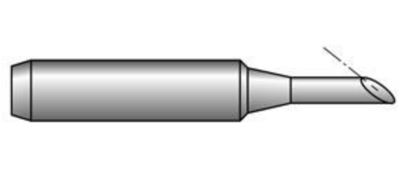
Beveled tips take a cylindrical tip and basically slice it at an angle. This creates a relatively large tip surface that is flush with the PC board when the iron is held at a comfortable angle. This tip can be loaded with molten solder and will make good pin contact when dragged down the board. It’s also a good tip to use when cleaning or de-soldering with wick as it gets lots of heat right where you need it.

There is also a “more advanced” version of the bevel tip, which is a concave bevel tip. This tip is specifically designed for use with SMD drag-soldering, as the concave tip creates a reservoir that holds plenty of molten solder and gradually dispenses it as you drag the tip down a row of pins. This is the type of tip I used and I am mostly pleased with it. It does take a bit of practice to get the solder well to actually make contact with the pins, but it works beautifully when used correctly.

The final important bit is the solder. Using the drag technique with a bevel tip requires that your iron be loaded just the right amount of solder: apply too much and you get bridges. Using the SMD well tip seems to make this a non-issue, as I melted lots of solder into the well and only created the 2 bridges across 4 parts that I’ve soldered so far. In fact, I found that I had to be careful to make sure I melted enough solder that it actually made contact with the pins.

Also in my research I saw many claims that the solder wire diameter was crucial, as well as plenty of advice to use “63/37” solder. This fraction refers to the solder’s composition. Traditional hobbyist “60/40” leaded solder is made of ~60% tin and ~40% lead. This ratio is only approximate and results in inexpensive solder that has a wide range of potential melting points. 63/37 on the other hand, is a more precise mixture and melts at a slightly lower temperature (183C) than 64/40. After using it to construct two REX boards, I have to say that I’m convinced of 63/37’s superiority over 60/40. It flows very well and bonded quickly.

Finally, it’s vitally important to use a good quality, temperature-controlled soldering iron. You don’t have to spend lots of money on a Metcal or Pace – go for an entry-level model from one of the quality brands like Weller or Hakko. Sure, their roughly $100 price tag is triple that of a cheap plug-in-the-wall soldering pencil, but the difference is easily worth it. Not only do they regulate temperature properly, they heat up quicker and have easily interchangeable tips. I set my station at ~320C.

For reference, these are the exact tools and supplies I used:

  • Hakko 936 soldering station (this is EOL now, but the FX-888 is a direct, if aesthetically less pleasing, replacement)
  • Plato HS-0531 SMD flow tip
  • Chip Quick No-clean Solder Wire, 63/37, .020-inch diameter
  • MG Chemicals no-clean flux paste, in a 10 mL syringe


Building my First REX

As I mentioned in my first post, I’ve successfully built a REX based on the plans, parts, and directions available from Stephen and Brian. In the end, the process was not difficult, but it’s not “easy” either, so I thought I would write up some details about the actual construction process.

Instructions

The main instructions I followed are here:

http://tandy.wiki/Building_a_REX

These were compiled by Brian after his experience building his REX units, and include all the major steps needed to build one. The major steps break down as

  1. Shape the printed circuit (PC) board
  2. Solder the components
  3. Flash the CPLD firmware
  4. Program the flash memory

Getting the Parts

Another great thing Brian has done is locate suppliers for all the parts needed to build a REX. The bill-of-materials (complete list of parts needed) for the REX is actually quite small: 2 resistors, 1 capacitor, a voltage regulator, the CPLD, and the flash chip. However, the CPLD and flash chip can be somewhat difficult to find; both are “obsolete” parts, meaning that they aren’t made anymore. Brian created a single link to the supplier DigiKey which loads your cart with almost all the parts needed. Almost…

The flash chip used by the REX is an “old school” 8 megabit parallel NOR flash. Digikey doesn’t sell any compatible part, but there are still plenty out in the world that are available from other distributors. (We don’t have to take extreme measures to come up with these.. yet.)

The PC board is, perhaps, the easiest of the parts to obtain, since Stephen kindly made the board available from OSH Park, a hobbyist-friendly PCB house. The only minor issue is that they are only available in batches of three. The boards are very inexpensive, so if you’re not building three, it’s no big loss to have a spare board. In fact, having a spare might be really useful, considering the next step…

Shaping the board

image courtesy of Sparkfun.com

The Tandy 100 uses a special option ROM socket that accepts modules with castellated mounting edges, like the photo shown here (borrowed from Sparkfun). Unlike normal DIP ROM chips where pins are inserted into sockets, the Tandy option ROM socket has protruding tabs that connect with the half-moon holes in the castellated board. It’s easy to make a castellated board by just creating plated vias near the edge and then just cut or sand the board down until half of the vias are exposed. Easy… but tedious. I used 80-grit sandpaper to get most of the material off and then finished with something like 160 until I had a nice smooth edge. Then, you need to go over it with a sharp knife and cut off any remaining copper bits that have either folded into the vias or are hanging off the top or bottom.

Soldering to components

The REX is built with entirely surface-mounted (SMT) parts. To someone with little experience with soldering (and even for some with lots of through-hole experience) this can seem daunting. But, like all things that look like “wizard-level” skills, successful SMT soldering is really just a  combination of a special technique and the right tools. The technique I use is call “drag soldering” and the special tools are not expensive — just special. Of course, a certain amount of manual dexterity and experience using a soldering iron is required. I plan on making a dedicated post for my soldering technique and experience.

CPLD programming

The CPLD (complex programmable logic device) is a device with logic gates that be programmatically turned into any digital logic circuit that the designer wants. The ship from the factory in a useless state and have to be programmed to do anything useful. The process of “programming” the CPLD is the loading of the designer’s circuit into the device, giving it the intended functionality.

In the case of the REX, Stephen’s CPLD program (released as a .jed file) needs to be loaded onto the REX CPLD. This requires a special (although, again, not expensive) programmer from Xilinx and their programming software. As the REX uses an older CPLD, it only requires older, commonly-available, and inexpensive “Platform USB” programmers, available on eBay for around $25. In my case, though, another fellow on the Model 100 list actually sent me his programmer (along with a complete set of parts) in exchange for assembling some REX units for him. So I’ll be using this to program the REX units.

The REX board includes a set of vias to which the programming cable needs to be attached. They are arranged in an offset configuration which I’ve never seen before, but which is intended to help keep the cable pins in contact with the vias. I connect to these vias, I cut some wire-wrap pins to the correct length to insert into the programming cable and then make contact with the vias.

Flash programming

After the CPLD has been programmed, the REX is a functioning device. But, it order to do anything with it in the Model 100, you need to program some data into the flash memory chip. The design of the REX precludes programming the flash chip with an external programmer, so this is done directly by the Tandy 100 – “in-situ” as it were. The basic process is:

  1. Bootstrap TS-DOS in RAM
  2. Use TS-DOS to load the REX flash .CO program
  3. Run the REX flash .CO, which will load more files from a TPDD device and program them into the flash memory

That’s the basic process. I’ll document the individual stages later.

Happy RetroChallenging!

RetroChallenge 2017/10 – Bringing REX back to life!

It’s time, once again, for Retro Challenge. For those unfamiliar w/ RC, it’s a month-long personal challenge to do a project involving retro/vintage computers. It’s run twice a year, currently in April and October (although it used to have a different schedule). Entries are “judged” and there are “prizes”, but there are no winners and no losers — to borrow from the WOPR: The only losing move is not to play.

Previous entries on this blog documented by attempt at RC this time last year. Last year, my goal was basically to fix up a couple of my malfunctioning machines, and do some upgrades. I didn’t have much time last year to work on it, so I considered that RC abandoned-in-place, more or less. Eventually I got the machines running and all is right with the world.

This year, though, I have more concrete goal: Bring the REX back to life!

No, I’m not starting another Jurassic Park. The REX is the flexible option ROM replacement for the Tandy 100/102/200 portable computers. I plugs into the option ROM socket and allows you to load multiple option ROM images and switch them dynamically. It also does RAM backups to its flash memory. Basically, it’s like adding a 1MB SSD to your Tandy 100 and it’s awesome. More information can be found at http://bitchin100.com/wiki/index.php?title=REX

But, it’s not available from Club 100 anymore. Between the passing of Rick Hansen (RIP), and lack of available time by the members who took over Club 100, the REX has been out of production and out of stock for some time. Every so often, a person would ask about getting a REX on the Club 100 mailing list, but the answer was always that there were none to be had.

Then, back in Feb of this year, Stephen Adolph basically made DIY plans for REX available, along with board design, software and flashing instructions. Brian White took that material and ran with it, eventually producing a functioning REX unit. Brian then made a Bill of Materials available through DigiKey and posted very detailed instructions for DIY’ing a REX. This caught my eye, as I’d been wanting a REX for a while. But, the stars were not aligned, and the idea sat in my mailbox.

Until now…

Last week, I successfully built my first REX board. The construction involves very fine-pitch SMD soldering, as well as Xilinx programming and “in-system” programming in the Tandy itself. Another member on the list sent me supplies he had purchased earlier, intending to build one for himself, so I assembled it for him. There are several steps, but the overall process is not actually hard, and the REX worked on my first try! Needless to say, I was starting to get excited.

So, my RetroChallenge for 2017/10 will be to get REX out of “unobtanium” status and into the hands of anxious Tandy 100 users. Originally, I wasn’t going to do an RC this year, because I was going to work on the REX instead. For whatever reason, that didn’t seem like a “proper” RetroChallenge – it felt like more of a logistical process than a “retro” challenge. But, after more thought, I realized, it’s actually the perfect RetroChallenge. Doing a project like this will involve a lot of learning on my part, it’s information that will likely benefit the community, and there will be lots to document in this blog.

So, I’m in. Hopefully, in 28-ish days, the world may not have a new stock of REX boards yet, but REX will be well on its way back from “extinction”.

Sidetracked by 11GB of Model 100 documents

So, I haven’t had time to even get my Model 100 within 10 feet of a soldering iron to replace that suspect RAM chip. But, that doesn’t mean I haven’t been immersed in the ways of 8-bit computers. Eddie Edwards, on the Club 100 mailing list, posted an absolute treasure trove of Tandy Model 100 and related documents. Unfortunately, he ran into space and bandwidth restrictions with the various free cloud providers, so he couldn’t post it all. Turns out, he has 26 gigabytes!!! of documents – mostly book and magazine scans – that he wants to get archived for good.

The Internet Archive has done amazing work in preserving old computer books, magazines and software, and I figured that this material really belongs there. So, I’ve been working with Eddie to get his collection tagged and uploaded. So far, I have 63 items uploaded, representing something like half of what I’ve gotten from him so far, which is only 11 or so GB. I’m in the process of getting it all into a single collection. The Archive actually makes this a rather painful process, having to email links to their staff who are the only ones who can make a collection it seems.

But, there are some real gems, including this example in April 1984 Portable Computing Magazine of bar-coded BASIC programs. Look Mom – no more type-ins!

Anyway – check out the collection thus far: https://archive.org/details/tandy_books. Note that this is much more than just the material I uploaded, but the most recent 53 items are from this newly-found material.

Day 18 – Atari 400, SIO2SD, and Composite fail

RC2016/10 Day 18.

For some reason, October is the month where everything wants to be worked on. It’s been over a week since I’ve gotten some “retro time” so i decided to break out the Atari 400.

My Atari 400
Say what you will about it, but this picture won me $250 in Sophos’s retro week contest.

I’ve had this Atari 400 since I was probably about 8 years old. My dad had the first go at it with a soldering iron, taking it to 48k of RAM and adding that spectacular external 800 keyboard (in a hand-made case, no less). I did a quick-and-dirty composite video mod to this machine about 3 years ago so I could bring it to a retro gaming night, but the output was barely visible on the screen. So, this thing needs some love.

Shortly after “Brexit”, when the dollar gained nicely against the Euro, I purchased an SIO2SD and a stereo pokey mod from Lotharek. I also bought a second pokey chip from him, and he installed it in the stereo board for me automatically. Nice.

Stereo pokey mode
Am I the only one who calls this a Gumby mod?

For the SIO2SD, I went cheap and bought the bare board. I already have a chopped up SIO cable on the homebrew cassette interface that my dad built for the Atari. I can’t remember if we used the tape before getting the 810 disk drive, or if we just wanted to have the tape interface. I remember playing some educational games on tape and saving some BASIC type-ins to tape as well. Anyway, with this guy, I won’t need tapes anymore, so I can scrounge the SIO cable from it.

SIO2SD-bare_board
SIO2SD board before attaching the LCD module to the top header.

A few minutes of wire stripping (I love screw terminals) and I have an SIO2SD attached to my Atari. Time to play some games I haven’t played in over 25 years.

no_signal

Rats! Seems like the video signal from my composite mod is too crappy for this old LCD monitor to recognize. Time to break out the big guns.

No_signal_crt

Crud. No dice with the Magnavox CRT TV either. Guess either something’s come loose inside or my mod was even worse than I’d realized.

In any case, the Atari project will have to go back on hold until I can either redo the mod myself or install a video mod board. I’m really hoping that Bryan from AtariAge gets his Ultimate Atari Video board back into production. He’s re-working rev. D right now. If I have to wait much longer, I’ll probably just get a 7800 mod board from eBay and stuff it in as a stopgap.