As I mentioned in my first post, I’ve successfully built a REX based on the plans, parts, and directions available from Stephen and Brian. In the end, the process was not difficult, but it’s not “easy” either, so I thought I would write up some details about the actual construction process.
Instructions
The main instructions I followed are here:
http://tandy.wiki/Building_a_REX
These were compiled by Brian after his experience building his REX units, and include all the major steps needed to build one. The major steps break down as
- Shape the printed circuit (PC) board
- Solder the components
- Flash the CPLD firmware
- Program the flash memory
Getting the Parts
Another great thing Brian has done is locate suppliers for all the parts needed to build a REX. The bill-of-materials (complete list of parts needed) for the REX is actually quite small: 2 resistors, 1 capacitor, a voltage regulator, the CPLD, and the flash chip. However, the CPLD and flash chip can be somewhat difficult to find; both are “obsolete” parts, meaning that they aren’t made anymore. Brian created a single link to the supplier DigiKey which loads your cart with almost all the parts needed. Almost…
The flash chip used by the REX is an “old school” 8 megabit parallel NOR flash. Digikey doesn’t sell any compatible part, but there are still plenty out in the world that are available from other distributors. (We don’t have to take extreme measures to come up with these.. yet.)
The PC board is, perhaps, the easiest of the parts to obtain, since Stephen kindly made the board available from OSH Park, a hobbyist-friendly PCB house. The only minor issue is that they are only available in batches of three. The boards are very inexpensive, so if you’re not building three, it’s no big loss to have a spare board. In fact, having a spare might be really useful, considering the next step…
Shaping the board
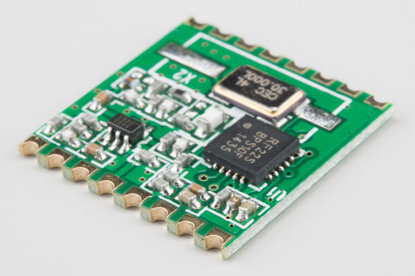
The Tandy 100 uses a special option ROM socket that accepts modules with castellated mounting edges, like the photo shown here (borrowed from Sparkfun). Unlike normal DIP ROM chips where pins are inserted into sockets, the Tandy option ROM socket has protruding tabs that connect with the half-moon holes in the castellated board. It’s easy to make a castellated board by just creating plated vias near the edge and then just cut or sand the board down until half of the vias are exposed. Easy… but tedious. I used 80-grit sandpaper to get most of the material off and then finished with something like 160 until I had a nice smooth edge. Then, you need to go over it with a sharp knife and cut off any remaining copper bits that have either folded into the vias or are hanging off the top or bottom.
Soldering to components
The REX is built with entirely surface-mounted (SMT) parts. To someone with little experience with soldering (and even for some with lots of through-hole experience) this can seem daunting. But, like all things that look like “wizard-level” skills, successful SMT soldering is really just a combination of a special technique and the right tools. The technique I use is call “drag soldering” and the special tools are not expensive — just special. Of course, a certain amount of manual dexterity and experience using a soldering iron is required. I plan on making a dedicated post for my soldering technique and experience.
CPLD programming
The CPLD (complex programmable logic device) is a device with logic gates that be programmatically turned into any digital logic circuit that the designer wants. The ship from the factory in a useless state and have to be programmed to do anything useful. The process of “programming” the CPLD is the loading of the designer’s circuit into the device, giving it the intended functionality.
In the case of the REX, Stephen’s CPLD program (released as a .jed file) needs to be loaded onto the REX CPLD. This requires a special (although, again, not expensive) programmer from Xilinx and their programming software. As the REX uses an older CPLD, it only requires older, commonly-available, and inexpensive “Platform USB” programmers, available on eBay for around $25. In my case, though, another fellow on the Model 100 list actually sent me his programmer (along with a complete set of parts) in exchange for assembling some REX units for him. So I’ll be using this to program the REX units.
The REX board includes a set of vias to which the programming cable needs to be attached. They are arranged in an offset configuration which I’ve never seen before, but which is intended to help keep the cable pins in contact with the vias. I connect to these vias, I cut some wire-wrap pins to the correct length to insert into the programming cable and then make contact with the vias.
Flash programming
After the CPLD has been programmed, the REX is a functioning device. But, it order to do anything with it in the Model 100, you need to program some data into the flash memory chip. The design of the REX precludes programming the flash chip with an external programmer, so this is done directly by the Tandy 100 – “in-situ” as it were. The basic process is:
- Bootstrap TS-DOS in RAM
- Use TS-DOS to load the REX flash .CO program
- Run the REX flash .CO, which will load more files from a TPDD device and program them into the flash memory
That’s the basic process. I’ll document the individual stages later.
Happy RetroChallenging!